Welcome to the 6-BM beamline at the Advanced Photon Source (APS) located at Argonne National Laboratory (ANL).
6-BM beamline provide brilliant, polychromatic x-ray beams for a variety of scientific applications. The 6-BM-A and 6-BM-B are accessible to outside users through various mechanisms including the APS General User program. For information pertaining to 6-BM-B, users are encouraged to contact COMPRES. 6-BM-A endstation provides energy dispersive diffraction and tomography capabilities. Users are strongly encouraged to contact the beamline staff before submitting a proposal to use 6-BM-A. |
||||||||||||||||
| Energy dispersive diffraction (EDD) | ||||||||||||||||
|
Energy dispersive diffraction (EDD) can be used to characterize:
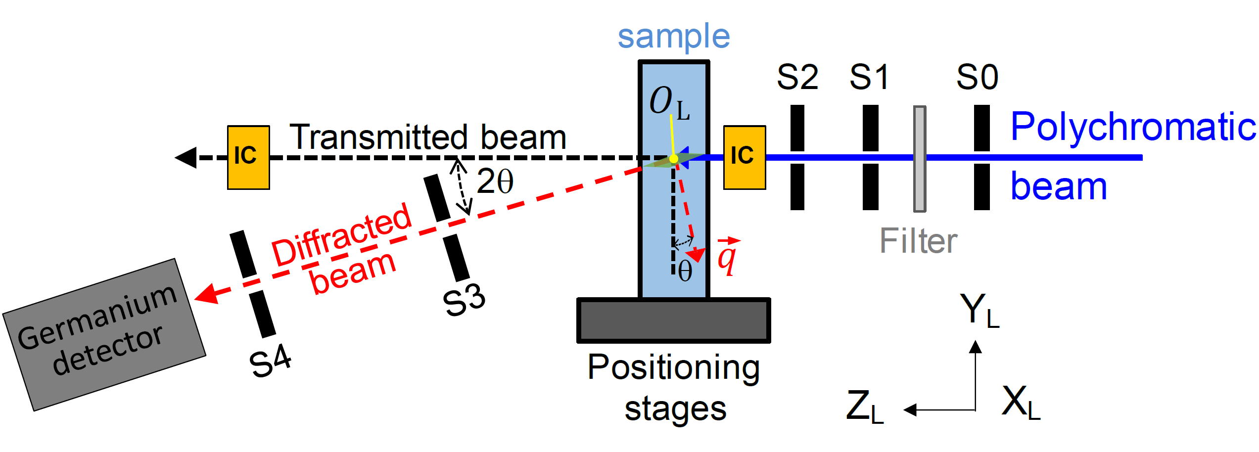
At 6-BM-A. the EDD setup employs a transmission geometry and germanium point detector(s) to measure quantities such as the phase composition and internal strains in a polycrystalline material. The experimental geometry is illustrated in the following figure.
In this figure, a series of slits (slits 1 - 3) reduce the size of the polychromatic x-ray beam from APS bending magnet and act as guard slits to reduce parasitic scattering. A set of filters hardens the x-ray beam to pick out only the high energy component of the polychromatic x-ray beam. Typically, two germanium detectors are used; the vertical detector is placed in the YL-ZL plane and the horizontal detector is placed in the XL-ZL plane. Both detectors and associated slits are setup such that they both point at O in space. This ensures that the same volume of material is interrogated by the two detectors. The distances between O and the detectors are approximately 1 m which translates to approximately 1 degree in azimuthal coverage. As a first order approximation, the size of the material interrogated (so called the gauge volume) is determined by the size of the slit openings and the scattering angle as illustrated in the following figure. As the measurement relies on having many grains in the gauge volume, the setup is optimized to maximize the gauge volume while ensuring that the required spatial resolution is met. Typical spatial resolution in XL and YL is approximately 20 um; in ZL is on the order of mm's. Typical strain resolution is on the order of 1 x 10⁻⁴. The positioning stages provide six degrees-of-freedom (DOFs) - translation along XL, YL, and ZL and rotation about XL, YL, and ZL. The rotations about XL and ZL are primarily used for sample alignment. The rotation about YL is the tomographic axis capable of 360o sample rotation. These states have micron-level (or better) motion performance with large motion ranges suitable for investigating a large sample. |
||||||||||||||||
| Application examples | ||||||||||||||||
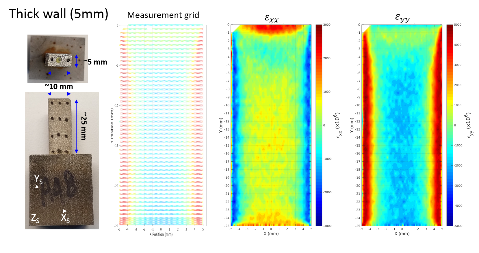
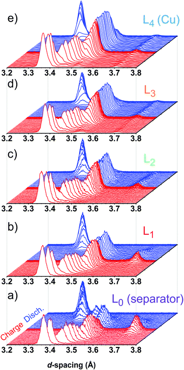
 Residual strain field in an additively manufactured component is often multi-axial and complex. 6-BM-A setup can be used to map the residual strain field in a bulk-sized sample non-destructively. (Air Force Research Laboratory (AFRL) Additive Manufacturing (AM) Modeling Challenge Series)  Complex systems like Li-ion batteries consist of multiple embedded sub-components that undergo complex changes during charge-discharge cycles. The EDD setup can be used to study the behavior of battery sub-components non-destructively during charge-discharge. L1 - L3 denotes different parts of graphite electrode in a battery. Quantifying lithium concentration gradients in the graphite electrode of Li-ion cells using operando energy dispersive X-ray diffraction - Energy & Environmental Science |
||||||||||||||||
| Tomography | ||||||||||||||||
|
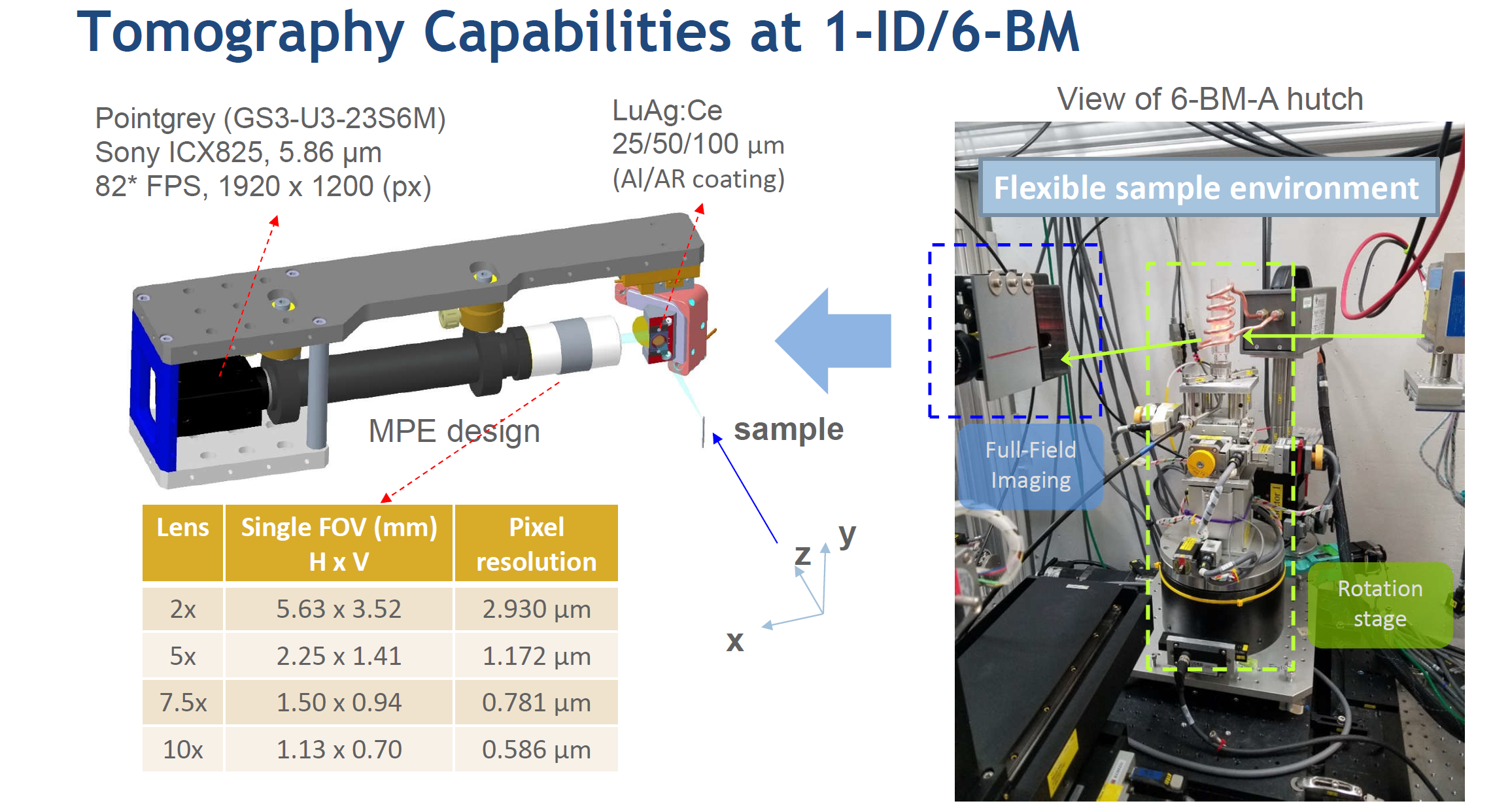
6-BM-A radiography / tomography capability combined with EDD offer a unique multi-modal view of the sample. Tomography at 6-BM is realized by the high-energy tomography camera setup developed at the APS. The field-of-view (FOV) and pixel resolution can be adjusted to meet the measurement needs. Stitching tomography is also available for larger samples that cannot be accommodated by 1 FOV scan.
|
||||||||||||||||
| Beamline Equipment | ||||||||||||||||
|
||||||||||||||||
| Control and data acquisition | ||||||||||||||||
| Beamline controls and data acquisition are done through EPICS and SPEC. | ||||||||||||||||
| Data access and analysis | ||||||||||||||||
|
Experimental data acquired at 6-BM-A is available through the APS data management system. Users are strongly encouraged to use this platform to access their data. For EDD, basic data visualization and analysis tools based on Matlab are available upon request. Typically, calibration data are provided along with these tools to facilitate the analysis. For tomography, reconstructions can be provided upon request. |
||||||||||||||||
| Contact | ||||||||||||||||
|
Users are encouraged to contact the beamline staff. Users with upcoming beam time are particularly encouraged to contact the beam line staff to discuss the scientific goals and experimental procedures.
|
||||||||||||||||
| Frequently asked questions | ||||||||||||||||
|
||||||||||||||||


