|
|
|
|
| Electromagnetic Variable Polarizing Undulator with Quasiperiodicity Capabilities |
| Device Length |
4.8 m |
| Undulator Period |
12.5 cm |
| First Harmonic Range |
- 250 to 2200 eV (Horizontal Linear Polarization)
- 440 to 2200 eV (Vertical Linear Polarization;)
- 400 to 2200 eV (Left and Right Circular Polarization)
|
| Higher Harmonics Range |
- 2200 to 3000 eV (all 4 polarizations; medium resolution grating only)
|
| Gap |
10.5 mm |
|
|
Quasiperiodic mode:
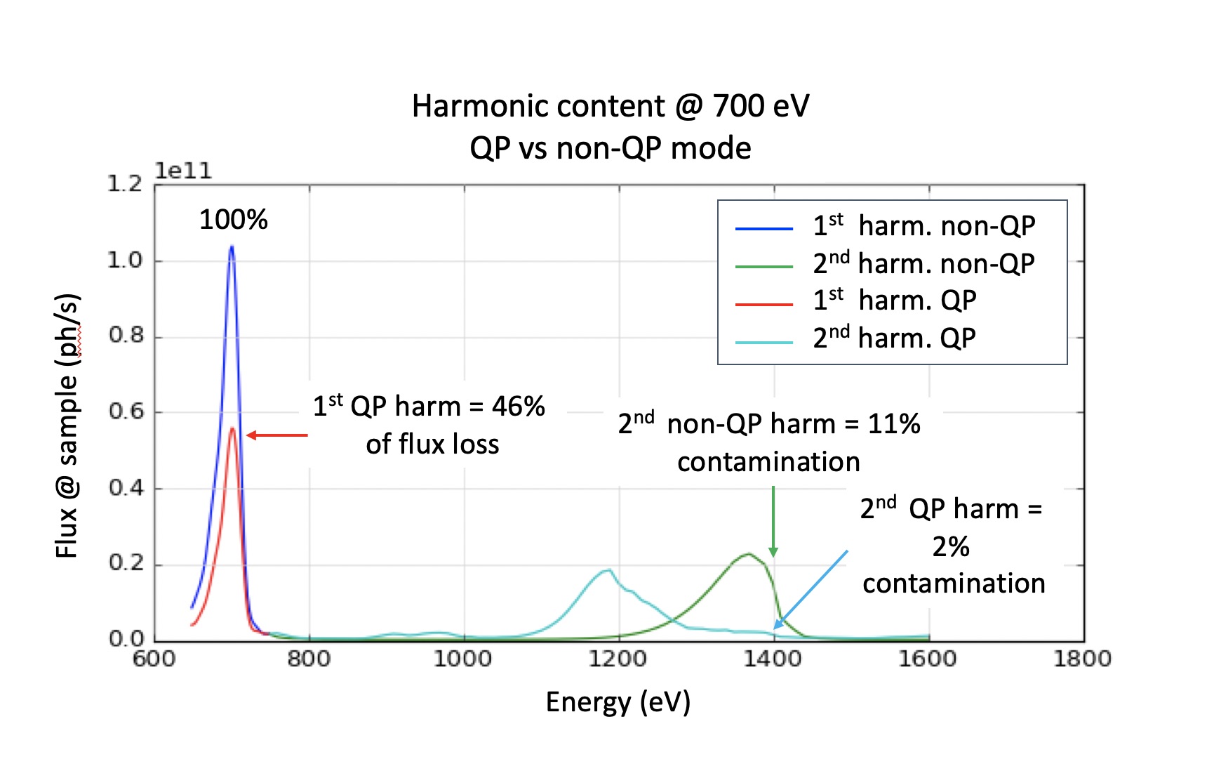
The IEX undulator can run in periodic (full flux) or quasiperiodic mode (QP) to reduce higher harmonics contamination. Running in QP mode results in a loss of flux on the first harmonic which varies depending on the energy and polarization. The trade off between harmonic reduction and flux loss can be tuned as needed. The example below displays the results obtain at 700 eV incident energy for a reduction down to 2% of the 2nd harmonic contamination in horizontal polarization. This mode is still in commissioning, so please contact staff in advance to communicate your needs before hand.

|
| Component |
Distance from Source
|
Comment |
| Mirror (M0) |
30.5 m |
Heat-sink, side bounce |
| Mirror (M1) |
31.3 m |
Heat-sink, side bounce |
| Monochromator (M2, MEG, HEG) |
39.7 m |
In-Focus VLS-PGM |
| Exit Slit |
59.7 m |
Both RSXS and ARPES |
| Mirror (M3A) |
64.3 m |
Horizontal Focusing (ARPES branch) |
| Mirror (M4A) |
65.1 m |
Vertical Focusing (ARPES branch) |
| ARPES focus |
66.3 m |
~ 30 µm x exit slit size (typically 25 µm) |
| Mirror (M3R) |
43.7 m |
Horizontal Deflecting and Focusing (RSXS branch) |
| Mirror (M4R) |
64.7 m |
Vertical Focusing (RSXS branch) |
| RSXS focus |
69.7 m |
~ 375 µm x exit slit size (typically 100 µm) |
|
|
| Grating |
k0 (lines/mm) |
cff |
Resolving Power
(E/dE) |
Flux (photon/sec) |
Energy Range (eV) |
| HEG |
2400 |
4.2 |
50,000 |
2 x 10^10 |
250 - 2,000 |
| MEG |
1200 |
2.2 |
10,000
2,500
|
2 x 10^11
2 x 10^9
|
250 - 2,000
2,000 - 3,000
|
| LEG (to be installed) |
400
|
1.5 |
2,500 |
4 x 10^12 |
250 - 1,900 |
|
|
|
|


